Plant time-lapse camera rig.
Two indexed M5 clevis joints, a supported desktop base, a slotted camera platform, and a separate 150 mm growth ruler.
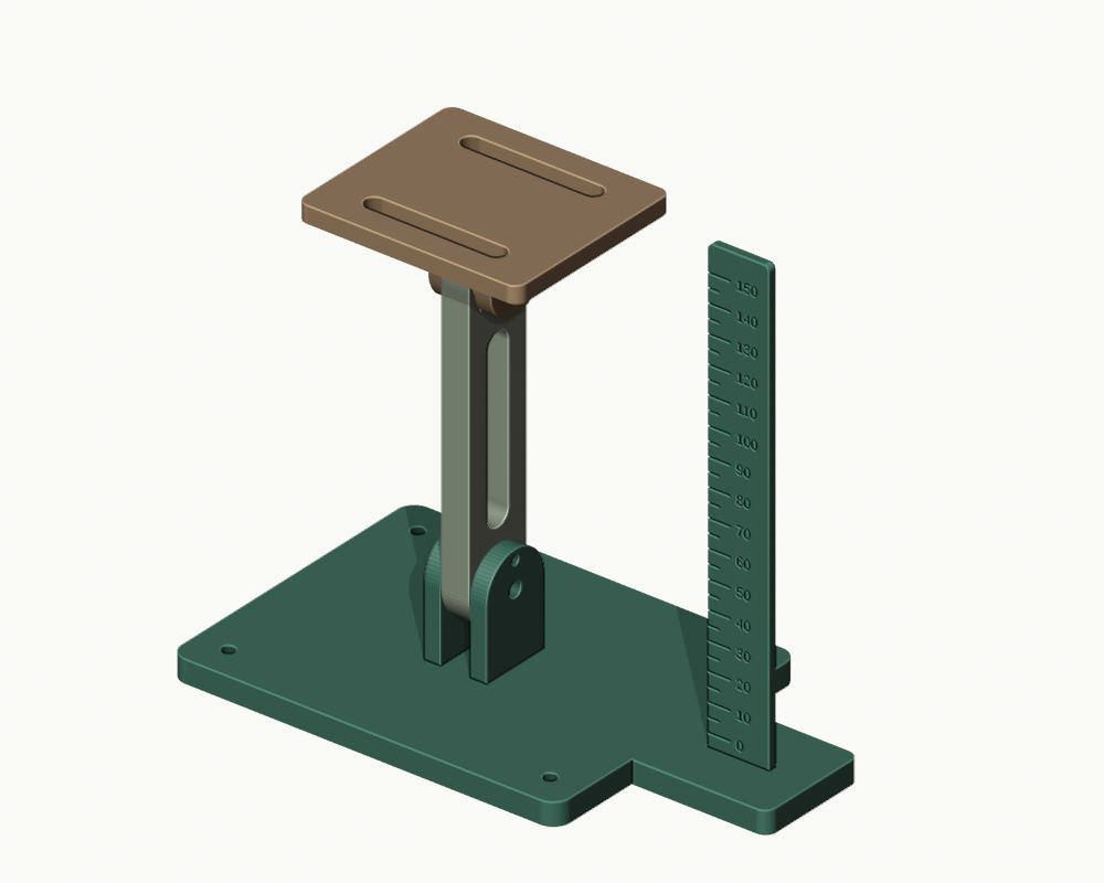
INTERACTIVE 3D PREVIEW
See it from every angle.
Loading 3D preview…
Drag to rotate · Scroll to zoomPLANT WORKSHOP / PROTOTYPE
Make and assemble.
All dimensions are in millimeters. These designs have passed digital mesh checks but have not been physically printed or tested. Check fit, water resistance, and load capacity for your setup.
Parts to print
- base × 1140 x 110 mm base; overall height 46 mm.
- arm × 1100 mm hole-to-hole, 10 mm thickness; flat on bed.
- platform × 180 x 70 mm; camera contact face prints on bed, cheeks upward.
- ruler × 122 x 170 x 3 mm; marks face upward; nominal 0-150 mm scale.
- ruler foot × 152 x 42 x 8 mm; open slot faces upward.
Additional components
- 2 x M5 x 35 mm bolts, 2 x M5 wing nuts or nyloc nuts, and 4 x M5 washers.
- 2 x smooth 3 mm alignment pins or M3 x 30 mm screws for positive 45-degree joint indexing.
- 1 x commercial 1/4-20 camera mounting screw and suitable washer, with thread engagement matched to your camera; printed slot is 6.8 mm wide.
- 4 x nonslip feet under the desktop base; optional M4 screws through base mounting holes to secure it to a board.
- Lightweight camera/webcam with a suitable tripod socket or a separately purchased adapter.
Assembly
- Place the lower arm eye between the base cheeks and insert an M5 bolt/washer/wing nut through the central holes.
- Fit the platform cheeks around the other arm eye with the second M5 bolt. Turn the platform so its smooth face points upward.
- Align a pair of 3.4 mm clevis holes with the desired arm index hole; insert the 3 mm pin. Eight holes per eye give nominal 45-degree repeat positions.
- Snug the M5 joints after the pins are fully engaged. Check that the arm and platform cannot slip under the actual supported camera weight.
- Attach the camera through one of the two slots using its correct 1/4-20 screw. Confirm that the screw does not bottom out in the camera socket.
- Insert the ruler lower edge 6 mm into the ruler-foot slot. Put the ruler in the same plane as the plant for consistent photographs.
- Keep the camera centered above the base. Secure the base to a board if any configuration moves the center of mass toward an edge.
Print notes
- PETG suggested; start with 0.20 mm layers, 5 walls and 40% infill for the base, arm and platform.
- All STLs are provided in print orientation. The platform camera face points down in its STL; flip it for assembly.
- Small horizontal bores may need reaming. Nominal arm/clevis side clearance is 0.3 mm per side.
- Ruler and foot can use 3 walls and 20% infill. Highlight engraved marks with a paint pen if desired.
Limitations
- PROTOTYPE / NOT PHYSICALLY TESTED.
- No camera load rating. This is a supported tabletop prototype, not an overhead or suspended mount.
- Ruler graduations are nominal modeled millimeters; verify against a physical ruler after printing. Camera perspective, shrinkage and alignment affect measurements.
- The zero graduation is 10 mm from the ruler lower edge, so it sits 12 mm above the desk after inserting the ruler 6 mm into its 8 mm foot.
- The preview excludes bought screws, pins, camera and nonslip pads.