Irrigation leak-catch tray.
A small catch tray with a removable rod guide, a bought foam float and a brightly colored printed rising flag.
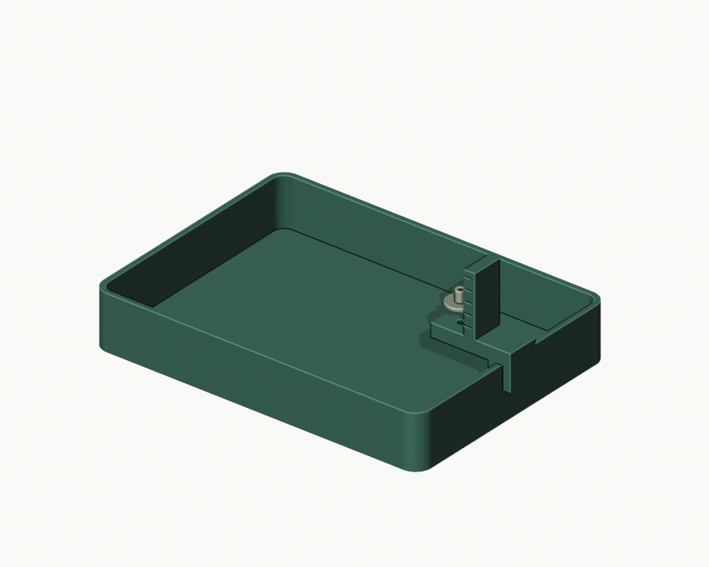
INTERACTIVE 3D PREVIEW
See it from every angle.
Loading 3D preview…
Drag to rotate · Scroll to zoomPLANT WORKSHOP / PROTOTYPE
Make and assemble.
All dimensions are in millimeters. These designs have passed digital mesh checks but have not been physically printed or tested. Check fit, water resistance, and load capacity for your setup.
Parts to print
- tray × 1148 x 108 x 24 mm, 2.4 mm wall/floor.
- guide × 1Printed on its side; 36 x 43 x 14 mm. 3.2 mm rim slot fits the 2.4 mm tray wall.
- flag × 112 mm diameter, 6 mm tall; 2.2 mm rod bore. Print in a visible contrasting color.
Additional components
- 1 x closed-cell foam float about 24 x 24 x 10 mm; choose foam that does not soak up water.
- 1 x straight lightweight 2 mm-diameter plastic rod or smooth skewer, initially 30 mm long.
- Small amount of adhesive compatible with the rod/flag and foam, if a friction fit is insufficient.
Assembly
- Leak-test the tray. Place it level underneath the fitting, with a clear path for drips.
- Slide the guide over the midpoint of the right long wall. The 3.2 mm slot straddles the 2.4 mm wall; the arm and rod hole point inward.
- Insert the rod about 5 mm into the center of the foam float. The float sits inside the tray, centered 24 mm inward from the outside wall, directly below the 3 mm guide hole.
- Pass the rod upward through the guide hole. Secure the flag near the top of the rod, with the flag disc above the guide arm. Keep adhesive clear of the sliding section.
- Add a little water and confirm the foam lifts the rod and flag freely without rubbing the tray or reference fin. Adjust rod length, deburr the hole, or reduce flag/rod weight if needed. Mark the dry position on the guide.
- The reference marks on the guide are 5 mm apart, for observing motion only. Empty the tray promptly after a leak is found.
Print notes
- Suggested PETG starting point: 0.20 mm layers, 5 walls, 6 bottom layers, 25% infill.
- Tray and flag print upright; guide.stl is already rotated onto its broad side. No supports intended; inspect the small horizontal guide bore in the slicer.
- Use a bright contrasting color for the flag. Confirm the bought float has enough buoyancy to lift both flag and rod.
Limitations
- Prototype, not physically tested. Closed STL topology does not prove a watertight print.
- This is a passive visual indicator, not a calibrated sensor or audible alarm. Some water must collect before the float moves.
- No hose restraint or pressure connection is provided. The tray does not prevent leaks or overflow.
- The foam and rod are bought components and are intentionally absent from the printable preview.