Adjustable watering-ring kit.
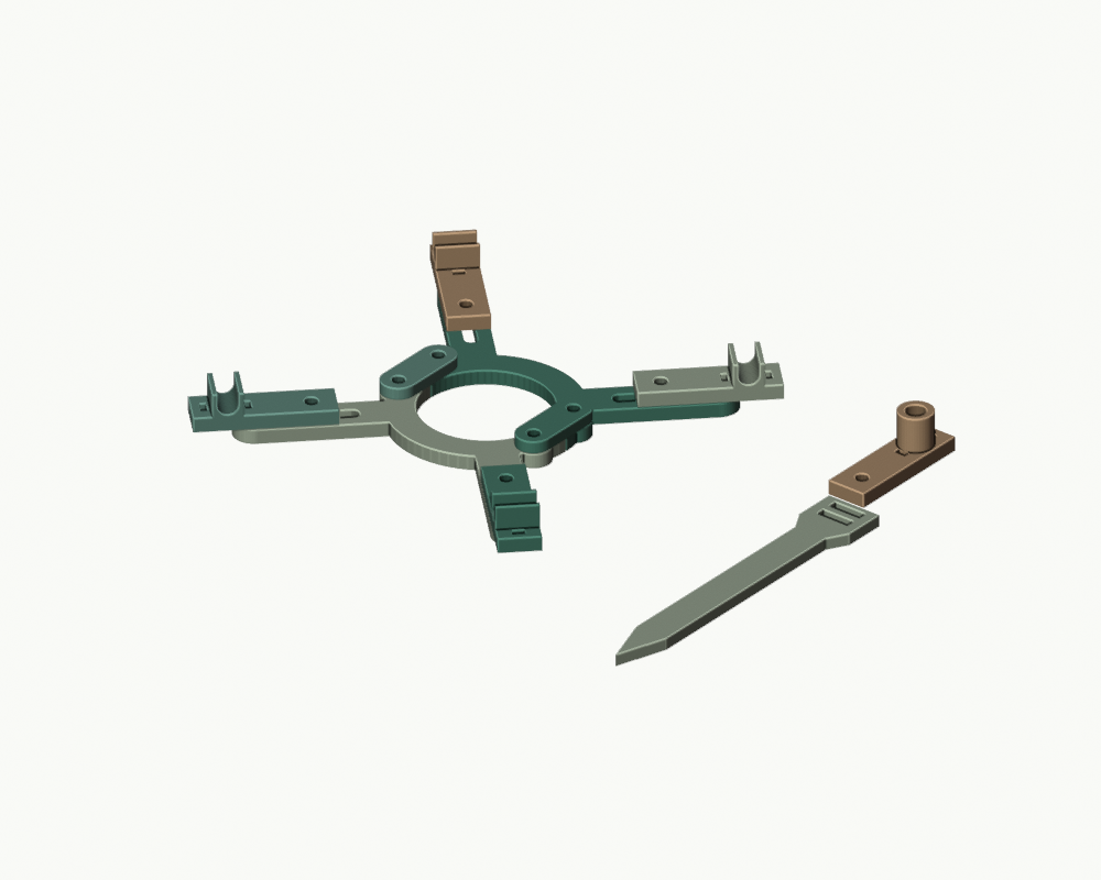
A split adjustable carrier for commercial microirrigation tubing, with sliding saddles, a replaceable vertical outlet guide and soil-support stakes.
INTERACTIVE 3D PREVIEW
See it from every angle.
Loading 3D preview…
Drag to rotate · Scroll to zoomPLANT WORKSHOP / PROTOTYPE
Make and assemble.
All dimensions are in millimeters. These designs have passed digital mesh checks but have not been physically printed or tested. Check fit, water resistance, and load capacity for your setup.
Parts to print
- hub half × 2Two identical halves form a carrier with a 44 mm plant opening and four slotted arms.
- joint bridge × 2Joins the split hub using two M4 bolts per bridge.
- guide slider × 4Open 6.8 mm tubing saddle; one M4 clamp bolt, plus a small zip tie at each saddle.
- outlet slider × 1Optional alternate slider: vertical 6.8 mm bore for a tube end. Replace one guide slider, not an additional mandatory assembly piece.
- support stake × 4120 x 20 x 4 mm maximum; print flat. Zip ties attach stakes to carrier arms.
Additional components
- 4 x M4 x 16 mm bolts for the two joint bridges; 4 x M4 x 20 mm bolts for sliders; 8 matching nuts and 16 flat washers. Use corrosion-resistant hardware where appropriate.
- At least 12 small zip ties, approximately 2.5 mm wide, for tubing saddles and stakes.
- Commercial flexible microirrigation tubing: nominal 6 mm outside / 4 mm inside diameter; about 0.6-0.8 m for a loop plus a separate supply line and short outlet drops. Measure your actual tubing before printing.
- Matching commercial tees and gravity-compatible emitters: one supply tee and, for a four-outlet loop, four outlet tees with four emitters. Buy a compatible complete tubing/fitting system.
- A separate low-pressure or gravity water source, a shutoff/flow-control valve and a catch tray for initial flow testing. No water source or emitter is printable in this kit.
Assembly
- Arrange two hub halves 180 degrees apart around the plant opening, both flat faces down. Keep the intentional 0.6 mm split between them.
- Put the two bridges over the pairs of holes at x=+/-27 mm, y=+/-10 mm. Install four M4 x 16 mm bolts, washers and nuts.
- Put a guide slider over each arm with its 6 mm tubing saddle pointing outward. Install an M4 x 20 mm bolt through the slider hole and arm slot; use washers on both ends and a nut below.
- Slide the four bolt centres to equal radii between 42 and 69 mm and align the sliders radially. Tighten by hand until the arms cannot rotate or slide. The tubing centreline then sits approximately 69-96 mm from the centre, or 138-192 mm nominal loop diameter.
- Thread bought tubing through the open saddles and use light zip-tie tension to retain it without pinching the tube. Use commercial fittings to form the loop, supply connection and emitter drops. The printed parts do not contain water channels.
- Push stakes into loose potting medium without disturbing major roots. Use two zip ties per stake to hold the carrier arms at the chosen height. The stakes and ties provide support; the carrier is not self-supporting above the soil.
- For a downward-facing loose tube end, substitute the optional outlet slider for one saddle slider and feed the tube through its vertical bore. A commercial emitter must control flow; the printed bore is only a guide.
- Run a low-flow test into a catch tray. Check all purchased joints, balancing and tubing retention before putting the kit over a plant.
Print notes
- All parts are in millimetres and lie flat on the bed as exported. Suggested trial: 0.20 mm layers, four perimeters, 25-35% infill, five top/bottom layers.
- Start with PETG for room-temperature watering use and trial-fit your actual tubing, bolts and zip ties.
- The horizontal guide saddle has an open top and needs a zip tie; it is deliberately not a rigid snap fit.
- Print one guide slider before the batch. Adjust tube_od in design.scad if actual tubing differs.
- A 44 mm centre opening suits smaller plants. Keep the carrier away from enlarging stems, and remove the split hub before it becomes restrictive.
Limitations
- PROTOTYPE / NOT PHYSICALLY TESTED. Clamping friction, stake stiffness and flow uniformity have not been established.
- The adjustable ring is a printed carrier for flexible bought tubing. The printed parts are not sealed fittings or pressure-bearing plumbing.
- The nominal supported loop diameter is about 138-192 mm; the loop is not constrained to a perfect circle between saddles.
- Four guide sliders are the default assembly. The supplied outlet slider is an alternate part, included as one spare, and replaces a guide slider when used.
- Emitters must suit the actual water pressure; many commercial irrigation drippers do not work from a low gravity head.