Adjustable trellis tensioner.
Hand-wound cord spool with twelve positive locking positions and an integrated cord guide.
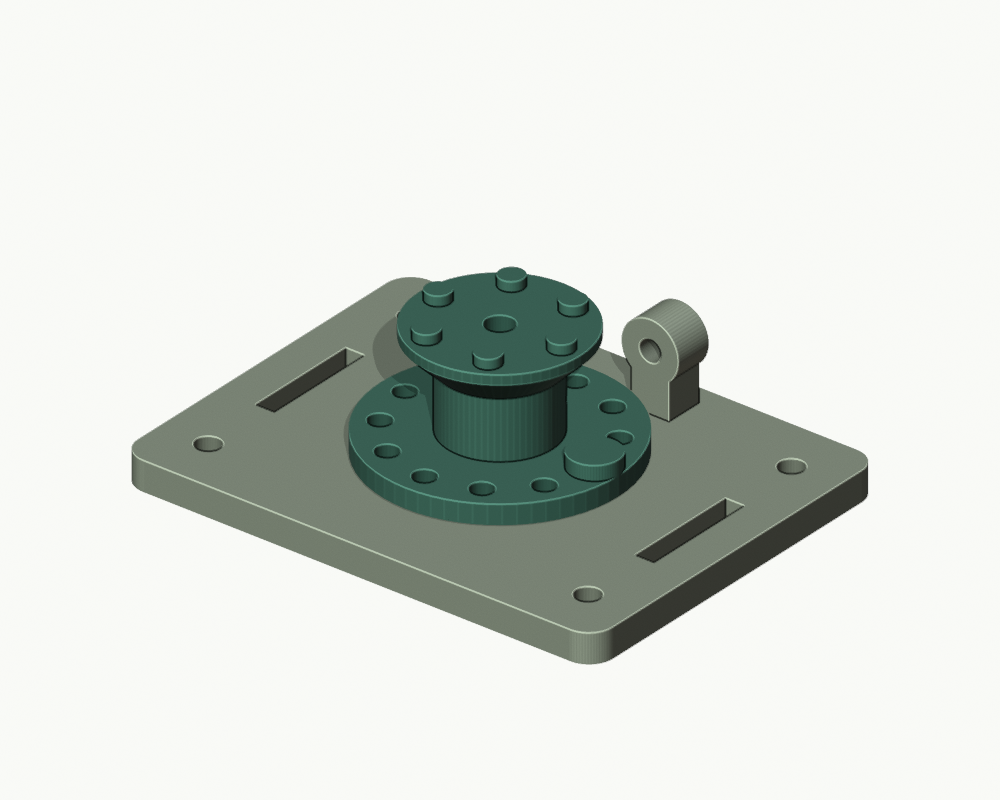
INTERACTIVE 3D PREVIEW
See it from every angle.
Loading 3D preview…
Drag to rotate · Scroll to zoomPLANT WORKSHOP / PROTOTYPE
Make and assemble.
All dimensions are in millimeters. These designs have passed digital mesh checks but have not been physically printed or tested. Check fit, water resistance, and load capacity for your setup.
Parts to print
- base × 1100 x 76 x 24 mm; flat face down.
- spool × 150 mm lower flange; flange down; M5 axle and twelve 4.5 mm lock holes.
- lock pin × 1Optional printed fit-check pin; head down for printing, invert for assembly.
Additional components
- 1 x M5 x 40 mm hex-head bolt, head across flats 8 mm; verify head fits 8.9 mm AF recess.
- 1 x M5 nyloc nut and 2 x M5 washers; use one ~1 mm nylon washer under the spool.
- 1 x smooth 4 mm steel drop pin, 9-10 mm usable length, with a removable head/handle (preferred over printed lock pin).
- Plant-support cord 1.5-2.5 mm diameter; cable ties or appropriate M4 mounting screws for your frame.
Assembly
- Secure the base to a rigid trellis using the two cable-tie slots or four mounting holes; mounting hardware depends on the frame.
- Insert the M5 bolt from below into the hex recess. Place a roughly 1 mm nylon washer above the base, then the spool and top washer/nut.
- Tighten the nyloc nut only until axial play is controlled; the spool must rotate freely and cannot be clamped solid.
- Pass cord through the guide, around the drum, then through the offset 3.5 mm cross-hole. Tie a stopper knot outside the drum. Keep cord away from axle and pin holes.
- Wind by hand, align a lower-flange hole with the single base locking hole, and insert the drop pin completely through both.
- To release, hold the spool, remove the pin, then unwind slowly by hand.
Print notes
- Use PETG as a starting material; 0.20 mm layers, 4 walls, 35% infill.
- Print each supplied STL in its existing orientation; the small horizontal holes may need light cleanup.
- The 45-degree upper flange reduces unsupported overhang; inspect the spool in the slicer.
- The optional pin is a fit-check part; use a steel pin for service.
Limitations
- PROTOTYPE / NOT PHYSICALLY TESTED.
- No load rating. For light plant-support net/cord tension only; not for lifting, fall protection, structural bracing, or overhead loads.
- Nominal rotary clearance depends on printing and washer thickness. Remove burrs and test operation before attaching plants.
- The guide center is 18 mm above the base bottom; the spool drum spans approximately 11-23 mm assembled.